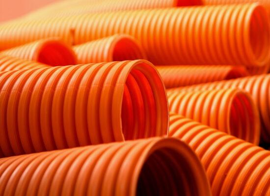
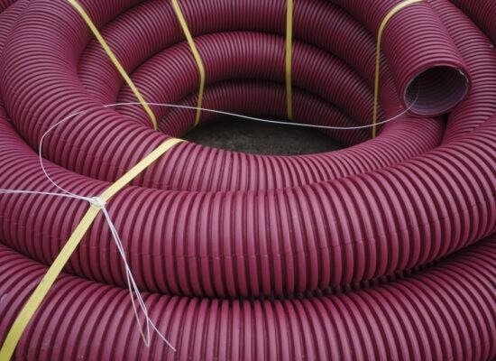
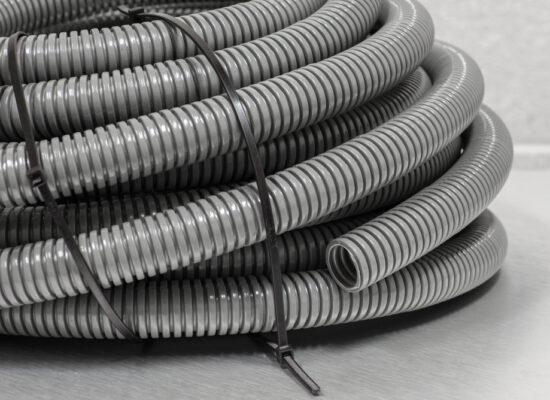
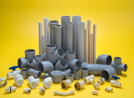
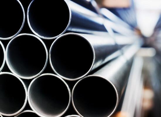
Pipes
Plumbing
Any system that permits the transportation of fluids is referred to as “plumbing,” often involving pipes, valves, plumbing fixtures, tanks, and other equipment. Gases like fuel gas may also be moved as a result of modern plumbing.
The Latin word for lead, plumbum, is where the word “plumbing” gets its etymology. This is so because the Romans utilized lead pipes, which were the first efficient pipes for moving water. Following the Second World War, copper pipe replaced lead due to heightened knowledge of lead toxicity.
The Romans were the first civilization to develop extensive plumbing systems, including aqueducts, the removal of wastewater, and other sanitary features, even though ancient Greek, Persian, and Indian cities had utilized simple kinds of plumbing.
Plumbing systems can be utilized nowadays for:
- Heatingand cooling.
- Waste
- Potable cold and hot water supply.
- Water recovery and treatment systems.
- Rainwater, surface and subsurface water drainage.
- Fuel gas piping.
A plumber is someone who installs and fixes plumbing and related fittings. Additionally, plumbers may work in management, consulting, teaching, design, and other fields.
Plumbers can earn the following credentials:
- Apprenticeships.
- Foundations
- National Vocational Qualifications(NVQs).
- Specialist
Plumbing Schematic
A plumbing drawing is a specific kind of technical drawing that offers information and a visual depiction of a plumbing system. It is utilized to communicate the engineering design to plumbers or other employees who will use them to assist with the plumbing system installation.
A plumbing drawing is used to clearly represent the locations of fixtures, sanitaryware, piping, valves, and other components, as well as to demonstrate how wastewater is to be collected and how fresh water is to be provided into a facility. The pipe runs are typically colored red and blue, respectively, to show the distinct hot and cold-water supplies. The grade (slope) should be shown on drainage pipe illustrations. A manhole schedule should include information about the name, invert level, cover level, and depth of any manholes that are present.
A shop drawing that shows how the prefabricated components will be linked, interconnected, and other details can also be used to detail plumbing.
Sanitation Pipes
Water from toilets, sinks, basins, baths, showers, bidets, dishwashers, washing machines, and other fixtures is transported out of a building through sanitary pipes and into the sewage system. Foul drainage and sewers are names for the equivalent subsurface pipes.
Every modern home is required to have a WC installed that is directly connected to the drainage system, as well as a basin installed next to the WC with a supply of hot and cold water, under the Building Regulations Approved Document G. Every house must also have a fixed bath or shower with a hot and cold water supply, and every appliance connection to the drainage system needs to have a trap to stop odors and potentially dangerous gases from accumulating inside.
The Building Regulations Approved Documents G and H and BS EN 12056:2:2000, “Gravity drainage systems inside buildings,” should be followed when designing a sanitary piping system. Calculation, arrangement, and sanitary piping.
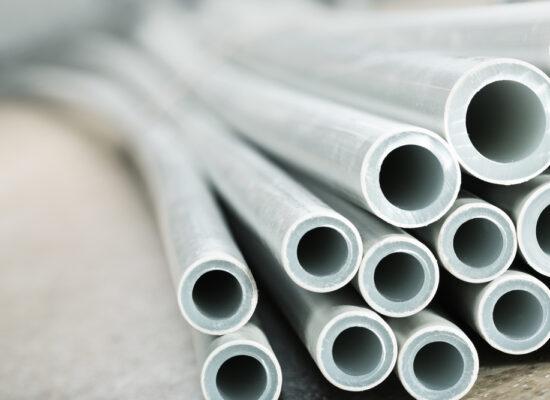
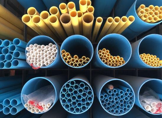
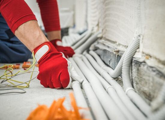
Traditionally, metals like cast iron, copper, or lead were used to make sanitary piping. However, modern designs primarily use polymers like uPVC, high-density polyethylene (HDPE), polypropylene, and others. Typically, they are joined together using push-fit fittings or some type of welding, such solvent welding.
Depending on the appliance to which they are connected, the pipes are made with varying sizes. For instance, a toilet normally utilizes a 110 mm pipe; bathtubs, showers, sinks, and washing machines use pipes that are 40 mm in diameter; a bidet uses a pipe that is 32 mm in diameter; and so on. In order to allow wastewater to drain away without leaving behind material and preventing obstructions, the pipes are set up to slope or “fall.”
A soil vent pipe (SVP), which is a vertical pipe frequently affixed to a building’s exterior and connects the drainage system to a point just beyond the level of the roof gutter to allow odors to be vented, is where sanitary pipework is typically linked. By venting the stack, system pressure buildups are prevented from damaging water seals in traps.
Sanitaryware
In extremely broad terms, the term “sanitaryware” or “sanitary ware” refers to sanitary equipment found in installations, such as toilets and bathrooms.
The term “porcelain” can be interpreted to refer, in the strictest sense, to toilet bowls, cisterns, bidets, urinals, and washbasins (and occasionally sewerage pipes), which have historically been made of porcelain, a ceramic material made of clay that, when covered in enamel, may be referred to as “vitreous china.” This is frequently white and goes by the name’s ceramic, porcelain, or china sanitary ware.
The term “sanitaryware” is sometimes now interpreted to include a wider range of appliances that might be found in sanitary installations such as baths, showers, bins, incinerators, macerators, and so on. However, sanitary appliances are now made from a wide range of materials, including metals, acrylics, glass, and so on.
Harvesting Rainwater
Rainwater harvesting (RWH) is the act of gathering and storing runoff from a catchment surface (usually a roof, though virtually any exterior surface could be suitable) for use as a substitute or addition to the city’s main water supply. As a result, less demand is placed on the mains supply, which provides some protection against local supply issues and lowers the energy needed for water treatment and delivery. As part of a sustainable drainage system, collection and redirection of surface run-off can help reduce the danger of flooding and regulate drainage (SuDS).
Rainwater is a relatively clean source of water and requires little processing (generally UV filtration). The water collected can be used for non-potable uses such providing washing machines, irrigation systems, car washes, sprinkler systems, and so on. According to some estimates, this method can replace up to 50% of home water supply and 85% of non-domestic water supply (ref Kingspan Water).
The Millennium Dome in London in 2000 used rainwater collected from the 100,000 sqm roof and filtered through reed beds in the landscape before being returned to the Dome and used to flush the 700 toilets. Rainwater harvesting systems range from the simple water butt used to water domestic gardens to schemes like these. In this instance, “greywater” from handbasins was also recycled, and groundwater from the Dome site was added to the water supply.
Policy
In urban water management techniques in the UK, rainwater harvesting is becoming more and more crucial. In October 2012, Schedule 3 of the Flood and Water Management Act 2010 was enacted, requiring sustainable drainage of surface water to be included in developments that require planning approval or have drainage implications. This is because it is thought to play a significant role in “Future Water,” the government’s water strategy (see sustainable urban drainage systems).
The Code for Sustainable Dwellings includes rules to limit surface water runoff for new buildings and promotes installing underground rainwater collection tanks on newly constructed homes. Additionally, the BREEAM and LEED rating systems give rainwater collecting good marks.
Standards for the installation, testing, and upkeep of rainwater harvesting systems for non-potable purposes are set forth in BS 8515:2009, “Rainwater Harvesting Systems, Code of Practice.” It covers specifications for filtration, storage tank construction and installation, and a number of methods for estimating tank sizes. Additionally, Annex C specifies pipework’s color standards so that it may be distinguished from the mains supply.
Types of System
Rainwater harvesting systems come in three primary categories:
- Water that is gathered in storage tank(s) and pumped straight to the location of need.
- Water gathered in tank(s) of storage and supplied by gravity to locations of usage
- To feed water to the sites of use, it is collected in storage tank(s), pumped to an elevated cistern, and then gravity-fed.
Due to the fact that home buildings do not require a long pumping distance, the first option is practical. The second or third approaches are likely to be more effective for larger commercial buildings. Large buildings may employ multiple storage tanks.
In-slab tanks that are a part of the building structure, plastic matrix tanks, large-volume bladders, and more traditional below-ground tanks made of ferrocement, or glass-reinforced plastic can all be used to store collected water thanks to innovative tank design. Numerous tanks can be connected together to increase the volume stored, improve final water quality (by further settlement), or just spread the expense (the storage component is typically the most expensive part of a rainwater harvesting system). Scaling the storage tank adequately buffers against irregular rainfall patterns.
While often suited to the tropics or “rainy” locations, rainwater collection devices are widespread and can be used in desert or semi-arid regions.
Green roofs
Although the amount of rainwater that may be collected from green roofs will be significantly less (little rain events may not cause any run-off), some substrates may be more conducive to collecting rainwater than others, particularly those with a high mineral content.
The quality of the water is inferior to that of water obtained from a “typical” roof due to leached nutrients, vegetative matter, sediments, and organic load (including bacteria). Avoid using fertilizers that could contaminate the soil. The primary issue, however, is the tendency of rainwater collected from a green roof to turn brown. For this reason, it is advised that the collected water be used for irrigation outside of buildings, where discoloration is less of a concern.
Calculations
The Environment Agency offers the following shortcut for calculating the size of storage tanks for residential buildings:
Storage tank volume (liters) = annual precipitation (mm) x effective collection area (m2) x drainage coefficient (%) x filter efficiency (%) x 0.05
Where: The average annual rainfall is given in millimeters (mm).
The area of the roof serves as the effective collection area.
The kind of roof affects the drainage coefficient (see below).
Manufacturers often specify a 90% filter efficiency.
(The storage tank’s volume in cubic meters can be calculated by multiplying the response by 1,000.
Pitched roof: 0.9; Pitched roof with riles: 0.8; Flat roof with gravel layer: 0.8; Drainage Coefficients)
The British Standard Code of Practice 8515:2009 – Rainwater Harvesting Systems provides guidance for non-domestic buildings. This provides a more in-depth approach based on more precise demand data, which is important because demand varies throughout the year, as well as specific rainfall data, like the area’s daily rainfall for the previous five years. A computer model that forecasts the system’s probable behavior over time uses these numbers next.
When designing storage tanks for their systems, UK suppliers of rainwater harvesting systems frequently employ shortcut techniques (ref 10). However, ‘Rainwater Harvesting: Model based design-evaluation’ explores more thorough models that are more suited to the design of RWH systems and their performance (Ward, et al., 2010).
Roebuck has created a thorough evaluation of modeling techniques (ref 5). Roebuck demonstrates that earlier analyses of the cost-benefits of rainwater collection systems were incorrect and lacked thorough research. All potential costs must be taken into account in the financial analysis in order to adequately assess the viability of a rainwater harvesting system. In addition, the cost of mains water has been rising and is likely to do so for the foreseeable future.
Cost-Benefits
A number of factors can be used to determine potential savings, including:
– The volume of rainwater that can be gathered.
– The presence or absence of a water meter on the property.
– The price of upkeep for the system.
– The price in energy incurred during pumping rainwater collection. Ward, et al. (ref 4) have devised a method to calculate the energy costs related to pumping rainwater. It makes the assumption that the system in use includes a header tank and compares the amounts of collected rainwater to pump specifications to calculate the energy consumption of the pumps.
– Capital for system-wide investments.
– The price of replacing a pump.
– Upkeep expenses.
– Charge for the mains water supply.
Large commercial buildings are more likely to save money since they typically have a larger roof catchment area and a higher demand for non-potable water than private property.
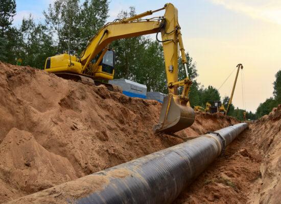
Drainage
Water can be artificially removed through drainage, even subsurface water. In civil engineering and construction projects, drainage is frequently a crucial component that must be included if flooding and other damages are to be prevented.
Drains often carry wastewater to sewers, which then transport it to an appropriate outfall or treatment facility. The following are examples of effluent in the context of building drainage:
Subsoil water
This is water that has been drawn out from the ground to raise the water table below.
Surface water
This is gathered from paved areas and surfaces like roofs.
Foul and soil water
This is effluent tainted with household or commercial garbage. The effluent from sinks and basins that does not include excreta is referred to as foul (or waste) water. The effluent from restrooms, toilets, and urinals is what is referred to as soil water.
Surface water and soil are regarded as being pure and can be soaked away or dumped into an authorized watercourse (such as a lake or river) without being treated. Before discharging, permission must be obtained from the appropriate authority or owner. Before being released into a watercourse, contaminated and soil water must be transported through sewer to a treatment facility.
Subsoil drainage
Subsoil drainage can be used to boost horticultural qualities for landscaping, lower a site’s moisture content, and improve ground stability. It can be necessary to drain the entire property or to protect a specific area.
Subsoil drainage is required by the Approved Document C of the Building Regulations in order to prevent ground moisture from entering a building’s interior or from harming the structure’s fabric.
In order to allow subsurface water to ascend into the pipe, subsoil drainage typically uses pipes that are perforated with a series of holes in the lower half or pipes that are porous to allow subsoil water to travel through the pipe body. Both are often laid dry joinedted in a trench of debris. Typically, a pervious membrane is laid as a filter mat on top of the debris, followed by regular backfill and 150 mm of topsoil.
Any additional lowering of the water table should be accomplished using other techniques because this form of groundwater control is only practical up to a depth of 1.5 m.
A cut off drain is typically placed when drainage is utilized to safeguard a building’s substructure because it stops the flow of water and directs it elsewhere.
Surface water drainage
Roofing
Building Regulation’s Approved Document H stipulates that sufficient arrangements must be installed to transport rainwater from a building’s roof. In order to accomplish this, roofs must be built with an appropriate fall towards a surface water collection channel or gutter that directs surface water to vertical rainwater pipes, which then link the discharge to the drainage system.
The required fall of the roof is dependent on the type of roof covering employed. Typical minimum recommended falls are:
- Aluminium– 1:60.
- Lead– 1:120.
- Copper– 1:60.
- Roofing felts – 1:60.
- Mastic asphalt– 1:80.
Standard “flat” roofs should be constructed with a minimum fall of 1:40 to obtain a finished fall of 1:80 while still leaving considerable building space for error.
Rainwater installation
Internal rainfall outlets and downpipes, as well as external guttering systems or hoppers, are typically used to drain rainwater from roofs. Even though the roof is tiny, it is advised to include at least two drainage points to reduce the likelihood that one may become blocked.
Drainage must be set up to prevent wetness or damage to the structure. If the rainwater pipe is installed internally, the couplings need to be leak-proof. If the roof is external, it should extend into and below the top of the gutter to stop water from blowing into the eaves.
Building downpipe discharges may:
-Be directly linked to a drain that empties into a soakaway.
– Directly attached to a drain that empties into a surface water sewer.
-Indirectly connected to a drain if the drain empties into a combined sewer via a blocked gully.
Cast iron has historically been the material of choice for home rainwater pipes and eaves gutters, but uPVC systems are becoming more and more popular because of how simple they are to install and how little care they require. They can be manufactured of other materials as well, such as aluminum alloy, galvanized steel, stainless steel, and others, as long as suitable size, strength, and durability can be guaranteed.
Paved areas
Surface water drainage is often offered in one of two ways for paved surfaces.
Collection of yard gullies
A paved area close to a structure is set up with a 1:60 fall into a gully. The size and quantity of gullies will depend on the type of area that needs to be drained and the design of the paved surface. Per gully, the maximum paved area should be 400 square meters. The yard gully should be blocked off if it is connected to a combined sewer with a least 50 mm water seal.
Channel connection
The paving is directed away from a building and into a channel that is directed toward the same 1:120 falls. The drainage system is linked to the waterway. Typically, the channel is
– A half-round, glazed clayware channel that can be either open or covered with grating.
– Precast concrete channel blocks: Top of each block has a continuous slot running down the middle of it.
– A square mesh grating made of cast iron is attached to the precast or on-site concrete box channel.
Highway drainage
The natural surface and subsurface drainage patterns of watersheds or hill slopes are impacted by the development of roadways. To avoid the buildup of extra water or moisture inside or on top of road constructions, which could harm their material properties, jeopardize overall stability, and endanger vehicle safety, it’s critical to provide adequate drainage. Drainage must handle water from surrounding catchment areas as well as the hard shoulders, foot and bicycle paths, and verges of the roadways.
Sustainable urban drainage systems
Traditional drainage systems may be supplemented or replaced with sustainable urban drainage systems (SUDS). They use methods to collect, store, and clean surface water runoff locally before enabling it to be progressively released back into the environment, imitating “natural” drainage.
© Arbemu. All rights reserved